386 Motherboard Repair - Part 1
Introduction
Back in 2021 I reviewed this excellent 386 motherboard - the OPTi 495XLC-based Data Expert EXP3406 - and was using it for a while as a "low-end" retro PC . The advantage of such late 386DX 32-bit boards is more around their flexibility to use a wide number of CPUs, high reliability due to their tight integration, and Level 2 cache capability.
Unfortunately, digging it out again it appears to be dead, so I thought I'd use this as an opportunity to write a troubleshooting article. No guarantees we'll get this operational again, but I will try. Please note that I am not an electronics engineer, so I am very open to suggestions and corrections in the approach I've taken in this article.
Here's the board:
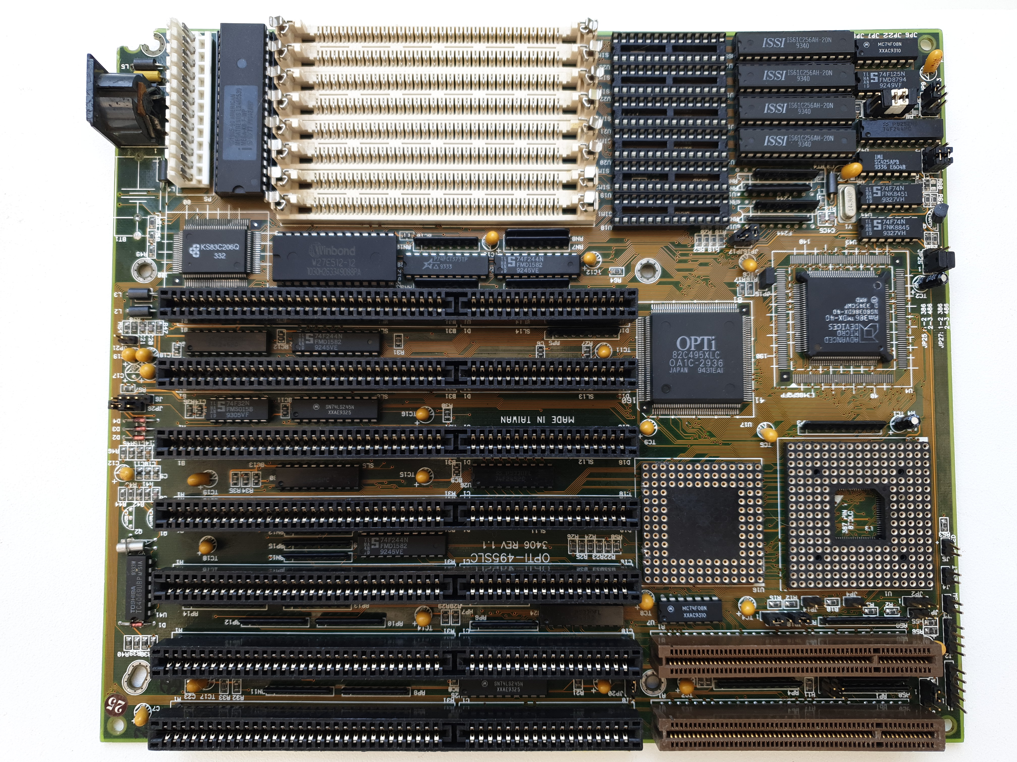
Data Expert 3406
(click for a larger version)
Initial attempt to start up
The first thing a 386 CPU will do on cold boot is try to execute the contents of the BIOS starting at address F0000h. If there's no evidence of this, e.g. on the BIOS address or data lines when you apply power, it could mean we have no clock, a bad CPU, a bad chipset (responsible for CPU-to-BIOS chip communication among other things), or possibly something else blocking one of the address/data lines. On this motherboard there are four primary ICs:
- OPTi 82C495XLC - the chipset
- Winbond W27E512 - the BIOS chip, in 20-pin DIP
- Samsung KS83C206 - the peripheral controller (also handles DMA, IRQ, RTC) - a rebranded OPTi 82C206, but in 100-pin PQFP form
- Am386DX-40 - the CPU
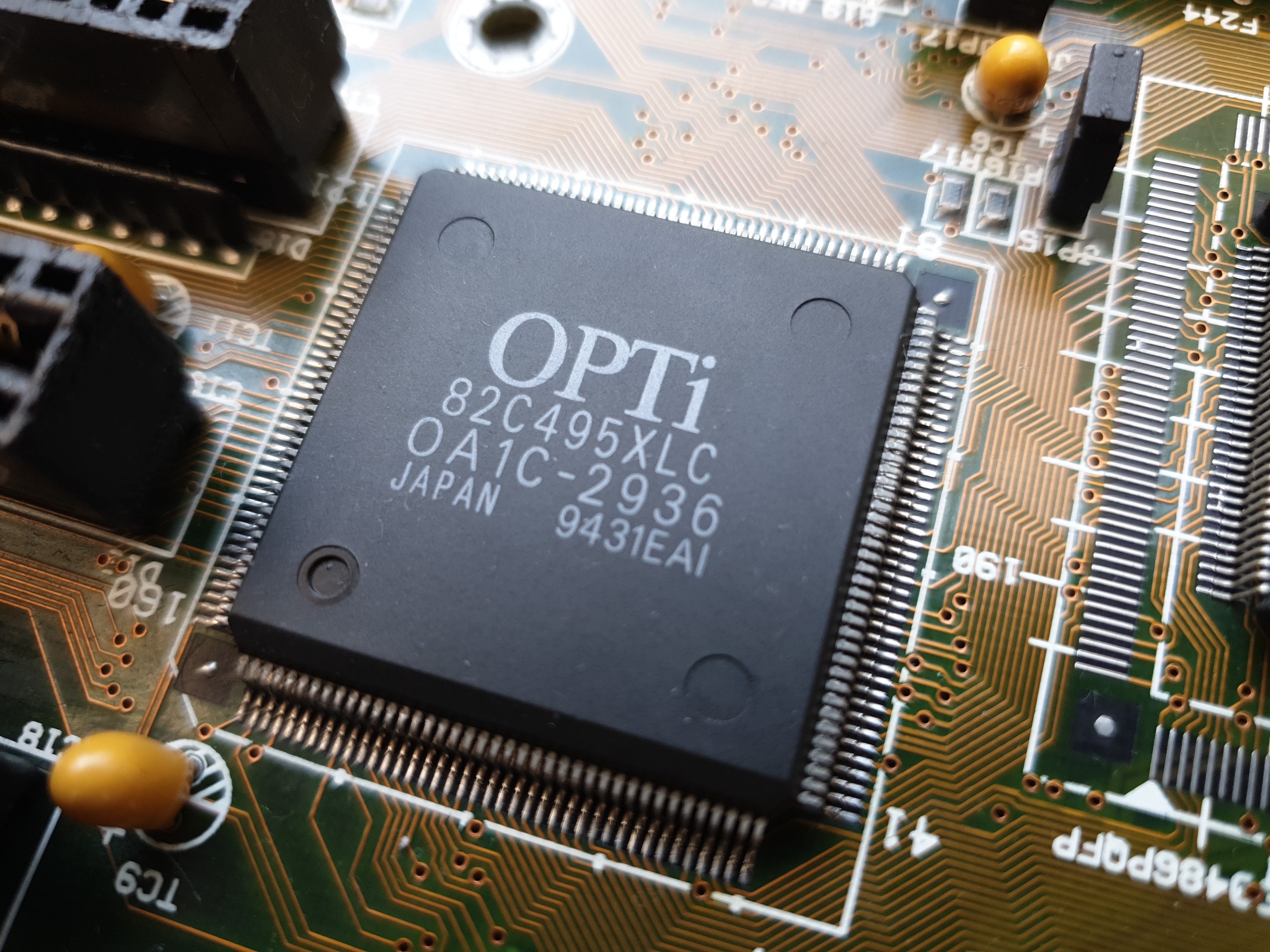
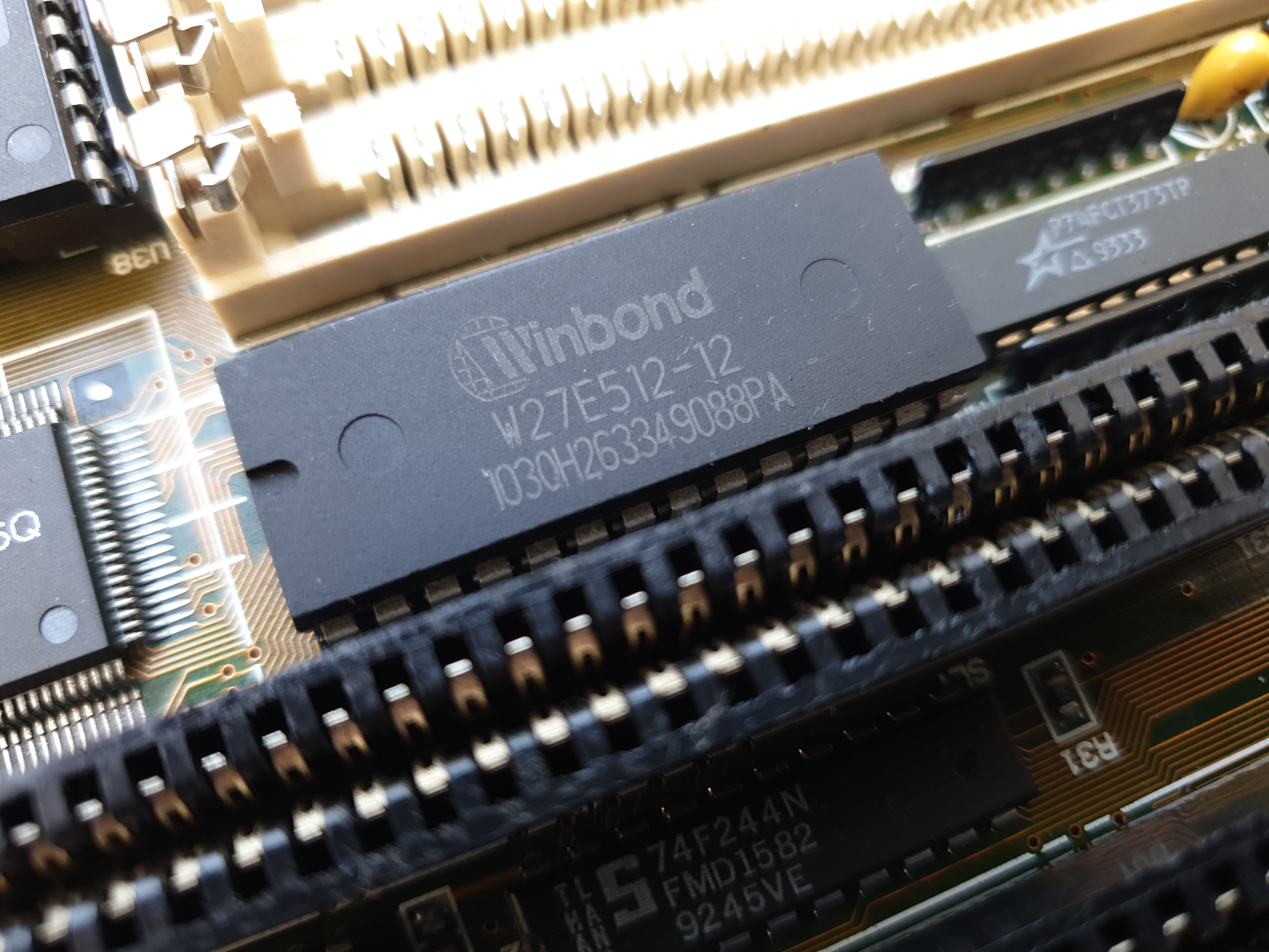
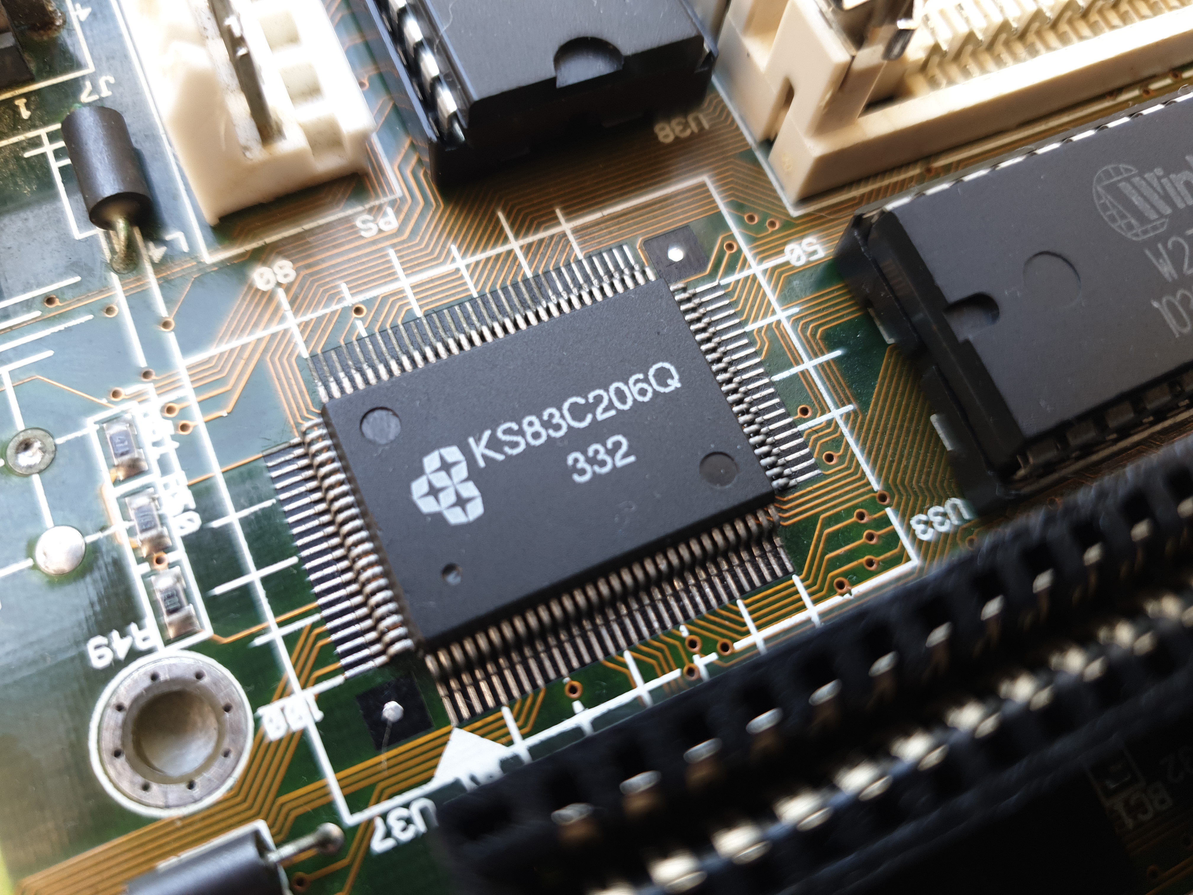
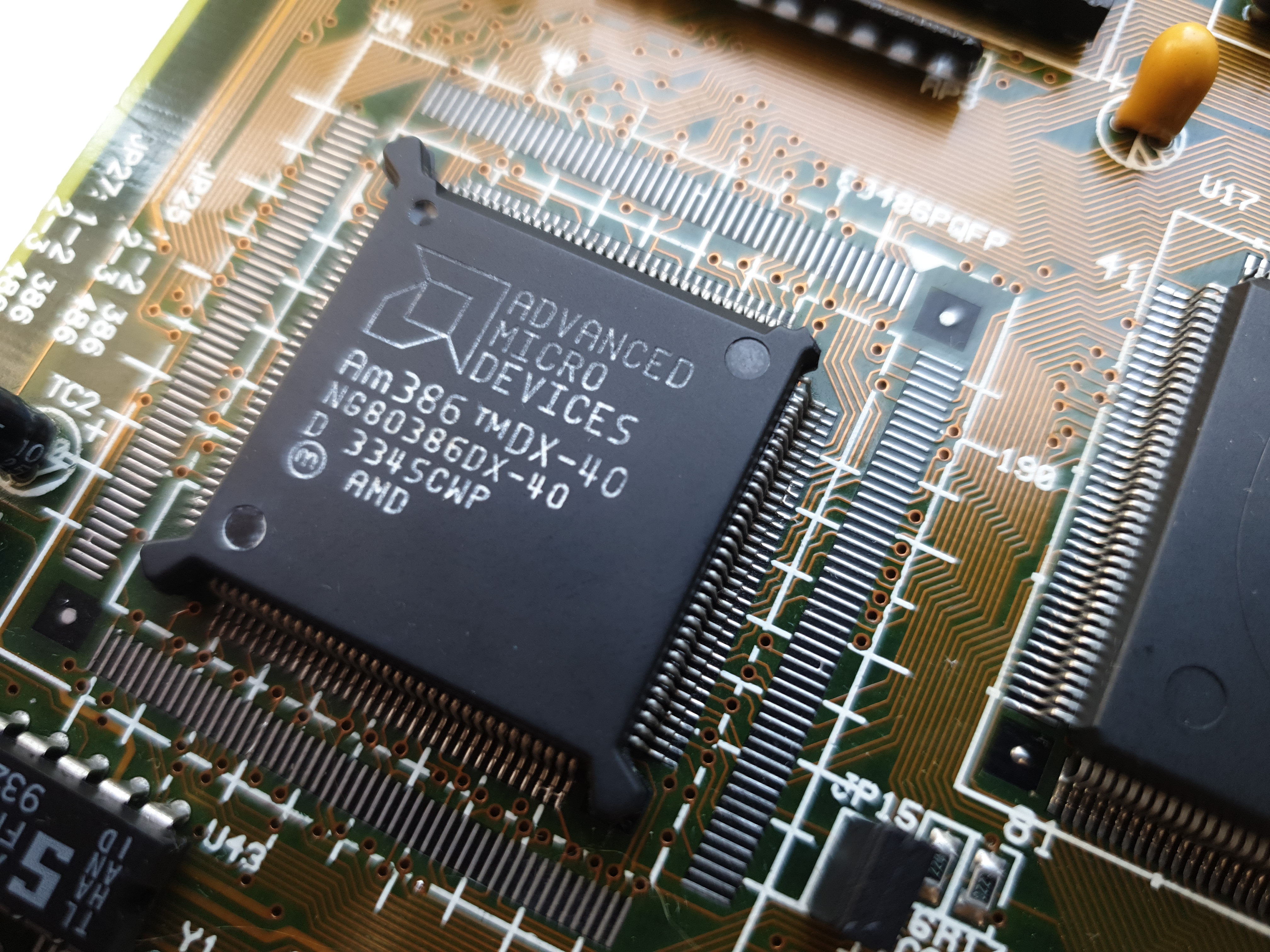
The primary ICs on the motherboard (click for larger versions)
And some prominent TTL logic chips:
- 74F244 - octal 3-output buffer / line driver
- 74F32 - 2-input OR gate
- 74FCT373 - octal 3-output latch
1) Power Supply
First check the power supply's output voltages on both the P8 and P9 connectors. These all look good.
| Block | Pin | Expected Voltage | Actual Reading |
|---|---|---|---|
| P8 | 1 (Orange) | +5V | +5.12v |
| 2 (Red) | +5V | +5.12V | |
| 3 (Yellow) | +12V | +11.98V | |
| 4 (Blue) | -12V | -11.30V | |
| 5 (Black) | GND | GND | |
| 6 (Black) | GND | GND | |
| P9 | 1 (Black) | GND | GND |
| 2 (Black) | GND | GND | |
| 3 (White) | -5V | -4.65V | |
| 4 (Red) | +5V | +5.12V | |
| 5 (Red) | +5V | +5.12V | |
| 6 (Red) | +5V | +5.12V |
2) Motherboard Prep
To start testing, I want to have an empty motherboard. In fact, you dont need much to be installed to at least get a sign of life (CPU starting and trying to access the BIOS). So I've removed all the SIMMs, expansion cards, keyboard controller chip, the BIOS chip, and all the SRAM cache chips.
3) Check Voltage lines on AT Bus
Next I install the POST Analyzer Card and power-on. It displays '- -' on the POST card's 7-segment display, along with -12V, +12V, +5V, and CLK LEDs on. While the '--' isn't good, all the voltage line LEDs plus the CLK LED should be on all the time when you apply power to the board. Three of the other LEDs are irrelevant for this motherboard:
- The -5V LED may or may not be on, depending on what your PSU supplies - it's not essential to this board being able to start up.
- The IRDY LED may or may not be lit for ISA (IRDY is only used if the POST card analyser is used in a PCI slot, as it reads the IRDY signal pin on that bus).
- The same goes for the FRAME LED (it's for PCI only, so we can ignore).
4) Is the system stuck in RESET?
The RESET LED should turn on and then turn off shortly after (within a second or so). If the RESET LED remains lit all the time, it means the system is holding itself in a RESET state and won't start running any code. If you have a solid RESET LED, check the RESET circuit for your motherboard - this usually requires a 'POWERGOOD' from the PSU going high, upon which the chipset then asserts a CPURST signal to the CPU. Check both the chipset pin and CPU pin for this taking place. It could be either the chipset or CPU that's bad. Of course, while you're there double-check all the Vin and GND pins on both the chipset and CPU are as expected.
The IRDY, FRAME, and RESET LEDs are off (RESET very briefly lit and went out within about 200ms). Shorting the Reset pins on the motherboard light up the RESET LED until I release the short - this is good, as it means RESET is starting high and quickly being pulled low, which is correct in a working system.
The chipset takes a reset input on pin 106 (RST1) either from the 'Power Good' signal from the power supply going low or from the reset switch. This is used to reset the CPU. Its pin 13 (CPURST) outputs a reset to the CPU (386 or 486).
5) Does a connected keyboard blink its LEDs on power-on?
If it does but the PC seems otherwise dead, it means at least the CPU, CPU power circuit, and BIOS are fine - early on in the startup process, the BIOS initialises the keyboard - this resets the keyboard controller and makes the embedded chip inside the keyboard flash all 3 LEDs once, so for this to happen you need a working CPU and BIOS. Actually, I'm not 100% certain this is accurate - my IBM AT keyboard (Model KB-8296) always flashes its LEDs even without a CPU installed, so is likely doing its own self-test as soon as it gets power.
Shorting the Reset pins on the motherboard with power-on correctly shows RESET on the POST analyser card and goes out when I unshort the Reset pins on the motherboard. The keyboard LEDs do not flash after I release the Reset.
6) Do we have a clock?
If the CLK LED on your POST analyser card is off it means there's no bus clock signal being detected by the card. If it's on, that's great but also confirm the clock is getting to the BIOS, peripheral controller (which may also contain the DMA controller and interrupt controller) and CPU.
*** I cannot see where the source of the clock signal is coming from on this motherboard! There are two crystal oscillators, neither of which would be the clock source (which needs to be 2 x the CPU clock, so 80 MHz). My other Am386DX motherboard has an Avasem AV9107C clock generator IC which takes an input reference clock of 14.3 MHz and outputs a clock signal up to 120 MHz, but on this board no such clock gen is present.
Head over to Part 2 as we look for hot chips, and check the CPU and BIOS ICs are functional.