Graphics Cards
Introduction
Throughout the days of DOS an evolution took place in display technology which took us from text-only (seriously, no graphics at all) through to beautiful, lifelike graphics that aren't too far off what we see today. The first IBM PC, being very modular in design came with a "display card" that could be replaced or upgraded with ease. Without a display card the system would not be able to show anything to the user.
Third parties also produced expansion cards and video chipsets that were compatible with the standards set by IBM from the early days of the PC. Most of the key manufacturers have their own dedicated pages here at DOS Days - just head over to the DOS Hardware Index.
Performance
A computer's performance originally stemmed from the microprocessor's clock speed because nearly every operation was conducted by the CPU. As graphics-intensive programs (CAD, games, etc) came around, more burden was placed on a computer's graphics card. As time went on, Microsoft Windows and 3D games arrived, which led to the advent of 2D and 3D 'accelerator' cards.
The earliest PC graphics cards were 'full length' - they filled the IBM PC's chassis from front to back - and consisted of many discrete components with a single display controller chip and a small amount of DRAM to store the screen attributes. From 1987, it became more commonplace to integrate the majority of graphics circuitry on a card into a 'chipset'. Chipset manufacturers could sell their chipsets to OEMs (Original Equipment Manufacturers) to use on their own branded cards, requiring the OEM to need a much smaller quantity of other supporting components to produce a fully functional graphics card - the total component count could be reduced from over 200 to about 15. The chipset was typically either one or two chips. While the chipset does have a big impact on a card's performance, it's important to note that two cards that use the same chipset can still differ widely in overall performance.
Up to early 1992 all PC expansion cards used the ISA bus, which ran at 8 MHz - some motherboards supported overclocking to 10 or 12 MHz on this bus, but a lot of ISA cards weren't designed to run at these higher speeds. Naturally, a 16-bit VGA card is able to execute its graphics demands up to twice as fast as an 8-bit card because of the wider bus width (same clock frequency but twice as many 'lanes on the highway' to transfer data to and from the card).
From early 1992 until late 1993, VESA Local Bus (sometimes called "VL Bus" or simply "VLB") cards arrived, and these eclipsed ISA-based cards in terms of performance due to no longer being bound by the slow 8 MHz ISA bus. A VLB graphics card typically transferred data to and from the motherboard at 33 MHz.
In late 1993, PCI graphics cards took over from VLB, making the separation of expansion bus clock from system clock universal for all expansion cards. VESA Local Bus had proven to be unreliable at higher clock speeds. The arrival of AGP in 1997 was a derivative of the PCI standard, and returned us to having a dedicated slot for graphics (VLB was not explicitly for graphics cards, but that was the primary motivating driver to its inception). ISA cards continued to be produced until around 1995.
RAMDAC
Just as with sound cards, VGA graphics cards have a digital-to-analogue converter (DAC) - before IBM introduced the VGA standard, graphics cards produced digital TTL signals for display by a digital monitor, so there was no need to convert signals to analogue.
For graphics cards, the DAC is usually referred to as the RAMDAC (Random Access Memory Digital to Analogue Converter). These are used to store the colour palette (in embedded fast Static RAM), and to convert the digital colour 'codes' into an analogue signal that are then sent to an analogue monitor. Each colour code is made up of separate Red, Green and Blue (RGB) codes, and these codes are sent to separate embedded DAC circuits inside the RAMDAC which produce an analog voltage on that colour signal line to represent the given colour.
In the early 90s, RAMDACs were something to look out for, with RAMDAC manufacturers mentioned in reviews alongside a Super VGA card's actual board manufacturer. Key ones were the Edsun Continuous Edge Graphics (CEG), and the Sierra HiColor DAC.
Since the mid-90s, the SRAM (Static RAM) portion of a RAMDAC is usually bypassed, with the DACs being sent display data directly for True Color modes. In such cases, the SRAM-stored palette is retained only for backward-compatibility with older software.
The speed of a graphics card is more a case of the main chipset and supporting circuitry than the RAMDAC used. The RAMDAC and the size of the card's video memory have a greater bearing on the number of display colours and palette size available.
MDA
The first display card for the PC was launched in 1981 - the MDA (Monochrome Display Adapter) and was available for both the 5150 (IBM PC) and 5160 (IBM PC/XT). It was designed to connect directly to the IBM 5151 monochrome [green phosphor] monitor. The card also came with a printer port to work with IBM printers, so it was often referred to as the Monochrome Display and Printer Adapter.

The card came with 4 KB of video memory to store the screen attributes which are stored at memory address B0000-B0FFF, plus an 8 KB character ROM which held the character set images, though only 4 KB was actually used. The card could be accessed via I/O ports 3B0 - 3BF.
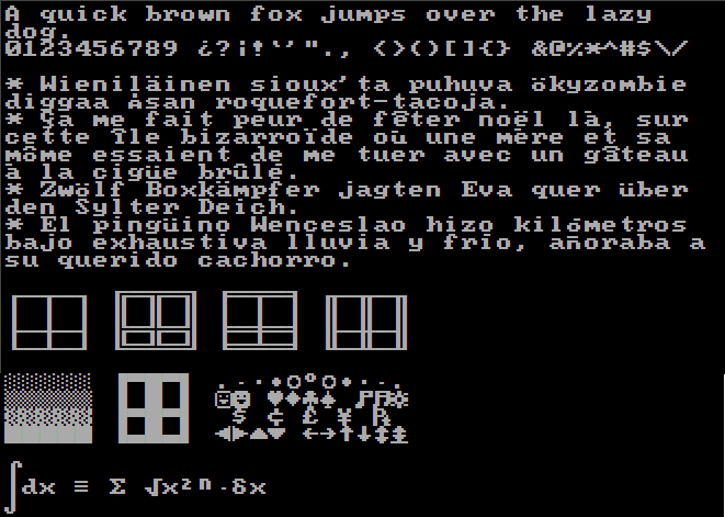
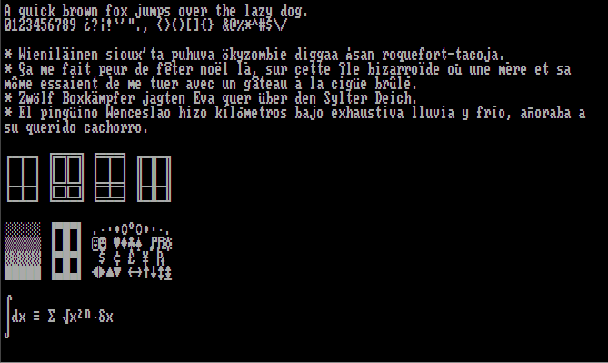
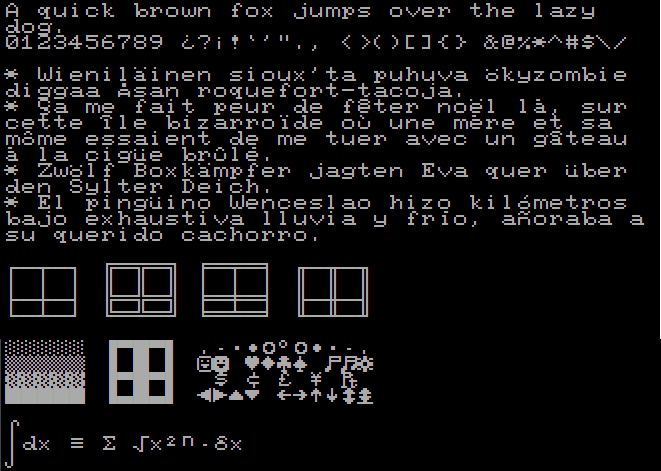
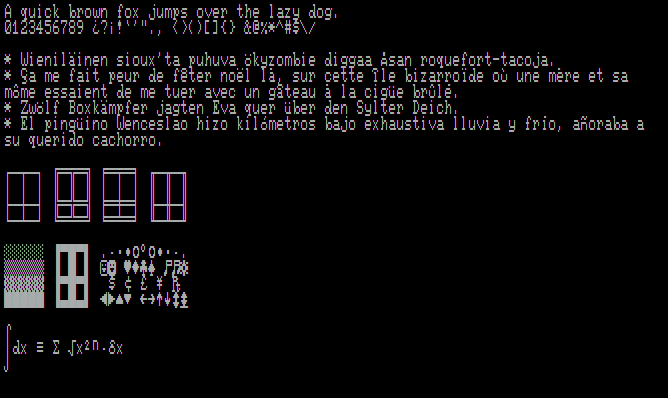
The MDA standard was intended to be used with a fixed frequency monitor, providing a 720 x 350 image format, although it was only capable of producing text output using its ROM-based character generator. These characters were "cells" of 9 x 14 pixels, so the image format is more accurately described as 25 lines by 80 characters each. This was known as 'mode 7', or 'mode 07h'. The character set was not redefinable. MDA cards that were sold in the USA contained what was called code page 437 - this was the set of characters that include all printable U.S. ASCII characters (32-126), extended codes for accented characters and some line drawing ones. For foreign markets, the ROM's character set was modified to suit Greek, Cyrillic, Hebrew and other characters.
![]()
The character set used by MDA
It uses a digital TTL output, meaning it fires either a 'high' or 'low', where a 'high' switches the CRT's beam on and a 'low' switches it off to create the characters. A separate 'intensity' output is also provided which could be used to change the brightness on a character-by-character basis.
It also provides a separate horizontal sync and vertical sync signal - something that is still retained in PC standards today. These synchronisation signals are required for CRT monitors and televisions to tell the The horizontal frequency used by the MDA standard is 18.432 kHz.
The MDA card could live happily alongside a CGA card (see below), but it's important to note that the MDA card can damage monitors that are not designed to take MDA video/sync signals such as the IBM 5153 (CGA) monitor and the IBM 5154 (EGA) monitor. When fitting different display cards into these older PCs you usually had to set some 'jumpers' or 'DIP' switches on the motherboard to tell it what was installed. Typically in an XT or clone, there was 8 DIP switches in 4 pairs. The third pair told the system what display card was installed: either monochrome, CGA, or no video at all. This setting used to confuse people, as for the more advanced display cards (EGA and VGA) you had to set the mainboard switches off. In fact, it was more logical than it seemed at first: the XT BIOS handled mono and CGA screens itself, but EGA and VGA cards had their own BIOS, so you needed to tell the onboard BIOS you had 'no video' in order to allow the EGA or VGA expansion card to have control.
On the MDA card itself were some jumpers. J1 is to be kept open, J2 is for an optional light pen, though IBM never released one of these themselves. If the card's bracket appears to be too large for your system it is because it was designed for the original IBM 5150, which had a wider spacing between expansion slots.
Also read my related section on MDA Monitors.
Hercules
The HGC (Hercules Graphics Card) became a standard of sorts as it fully supported MDA but added a high-resoultion monochrome graphics mode of 720 x 348 pixels. This was widely adopted in the early 80s, and actually outlived CGA it terms of usefulness over the years due to the high quality text mode from its MDA backward compatibility whilst also offering a high resoution graphics mode (albeit in 2 colours). It was often used in a dual-monitor setup with an MDA card outputting to one display and the Hercules card outputting to a second display. Dithering techniques were often employed by games and other software to produce what appeared to be shades to further differentiate the 2 colours. To support the graphics mode, a Hercules card came with 64 KB of video RAM - 16 times that of an MDA card.
For nearly 5 years, the Hercules card was the standard for monochrome graphics. Dozens of programs were rewritten to take advantage of its capabilities, including the one that made the Hercules card a success, Lotus 1-2-3. But in 1987, the introduction of the VGA standard challenged Hercules' dominance. In the long run, VGA will likely triumph as the graphics standard for both color and monochrome." PC Magazine, August 1989
Hercules cards used the same starting memory area as MDA (B0000h) to store the frame buffer (screen contents), but with the HGC's 64 KB of video RAM that used B0000h - BFFFFh, this would have overlapped a CGA card's video memory area which started at B8000h. It was possible to have both a CGA card and an MDA card in a PC at the same time to provide 2 monitor outputs side-by-side (one text and one graphics), so in order to retain full backward compatibility with this, Hercules cards defaulted to disabling the upper 32 KB so as not to cause this overlap.
CGA simulators allowed you to run CGA software with a Hercules card, mostly for games that did not provide a Hercules graphics option. These worked in several ways. For programs that wrote directly to the CGA memory area they would use the fact that this upper portion of the HGC's memory area was unused/disabled. A timer-controlled interrupt would "remap" the contents of the CGA memory area at B8000h to the HGC's lower memory area at B0000h as well as converting its content, e.g. the 4-bit CGA graphics colours to 1-bit dithered black & white and stretching the resolution, to display somewhat correctly on the Hercules monitor. Another method used by these utilities was to trap the video BIOS calls (in cases where they were used rather than 'direct' screen updates) and do the conversion when they were detected. Depending on your PC's performance, this could occur for every 'frame' being sent to the monitor - if not, the game would run more slowly, though some simulators had the option to drop frames in order to keep up. The only case where this would not work was when a game wrote directly to the CGA card's CRTC (CRT controller) registers, since a Hercules card did not have the same CRT controller chip as a CGA card.
CGA
Arguably the lowest-grade of early PC colour graphics was IBM's Color Graphics Adapter (CGA). Introduced in 1981 it was the first to be able to display colour, and the first to display graphics (dot resolution) rather than just character text. IBM intended that CGA be compatible with a home television set. The 40×25 text and 320×200 graphics modes are usable with a television, and the 80×25 text and 640×200 graphics modes are intended for a monitor.
It was designed to be connected to the IBM 5153 (IBM Colour Display) or IBM 5154 (IBM Enhanced Colour Display) monitor via a 9-pin D connector. It's important to note that the CGA card can damage monitors that are not designed to take CGA video/sync signals such as the IBM 5151 (MDA) monitor.

With its 16 KB of onboard video RAM, it could show 4 colours on-screen simultaneously at a graphical resolution of 320 x 200, or 2 colours at 640 x 200. You could choose from two palettes, which looked like this:
It was designed to connect directly to the "IBM 5153 color display", but could also be connected to a television or composite video monitor using an RCA connector.
The IBM CGA card stores its screen content at memory addresses B8000-BBFFF and uses I/O ports at 3D0-3DF. Just like the IBM MDA card, it also has an 8 KB character ROM chip (it's actually the exact same chip with, I believe, the exact same contents), of which 4 KB stores the MDA font, and two variants of the CGA font use up the second 4 KB in 2 KB chunks. At the heart of the CGA card, like its older MDA brother, is a Motorola MC6845 CRT controller chip.
The character ROM contains two different character fonts, both of which are square 8 x 8 pixel blocks.
The two CGA character fonts in 40-column and 80-column mode: 'thick' (top) and 'thin' (bottom)
Most graphics cards that supercede the CGA graphics standard offer either full CGA register compatibility, or may emulate some or all of the original CGA card's capabilities. To test how compatible one of these cards is, you can use CGA_COMP - a compatibility checker that runs in DOS.
Plantronics ColorPlus
The Plantronics ColorPlus card of 1982 provided a superset of the CGA standard, using the same monitor and the same resolutions. The Plantronics card has twice the memory of an IBM CGA card which can be used to double the colour depth, and provides graphics modes of 320 x 200 in 16 colours and 640 x 200 in 4 colours. It also offers a high-resolution text font. These are more or less the same as the PCjr/Tandy modes, but they require you to program the registers directly (no BIOS support). Some applications like Lotus 1-2-3 support them, but you can't use games configured to run in PCjr/Tandy mode.
Some third-party graphics cards could also display these "extended CGA" modes, usually describing them simply as "Plantronics mode".
Tandy/PCjr
When IBM launched the PCjr (model number 4860), it came with built-in colour graphics and 3-channel audio. Compared to the IBM PC or XT this was a marvel, since those required expensive expansion cards to achieve the same output.
The PCjr video output is compatible with all seven BIOS-supported CGA modes, plus additional 160 x 200 (16-colour), 320 x 200 (16-colour), and 620 x 200 (4-colour). The latter two, plus the 80 x 25 text mode require the optional 64 KB internal memory upgrade card, which doubles the PCjr's system RAM to 128 KB. Like CGA, PCjr video output is a composite signal that supports using a colour or black & white television set.
The main problem with emulating the Tandy graphics is that the video buffer is not in a fixed location. It moves up the more memory is in the computer.
When Tandy entered the PC clone market with their Tandy 1000 they liked the idea of having integrated video and audio circuitry, and so effectively copied the design of the PCjr.
EGA
IBM created the Enhanced Graphics Adapter (EGA) standard and released their card in October 1984 to coincide with the release of the new IBM PC/AT personal computer. Designed to connect directly to IBM's new Enhanced Colour Display, or ECD, monitor (Model 5154), it lasted as the best graphics standard right up to the release of MCGA and VGA standards in 1987 when IBM launched the PS/2 range of personal computers.

The card came with 64 KB of video memory and a 16 KB ROM, which permitted resolutions up to 350 lines in text mode. The EGA standard can handle up to 256 KB of video memory, allowing up to 64 colours on-screen at once. While the base card only had 64 KB of RAM, you could purchase the Graphics Memory Expansion Card into which you could plug a further 192 KB of DRAM chips via twenty-four 16K x 4-bit chips.
The EGA palette allows all 16 CGA colors to be used simultaneously, and it allows substitution of each of these colors with any one from a total of 64 colors, at a resolution of 640 x 350. Text mode was an 8x14 character box which could also display text in colour. The card ran at two frequencies: 22 kHz for the new 640x350 mode, and 15.75 kHz for compatibility with the older 640x200 and 320x200 modes. The EGA card includes a 16 KB ROM chip which extends the IBM PC system BIOS for additional graphics functions. It also includes a CRT controller chip that has a backward compatibility mode so the EGA card is able to generate video signals from earlier graphics cards.
Both the EGA card and ECD monitor were made available at launch to be sold to existing owners of the IBM PC and IBM PC/XT, as well as the new IBM PC/AT.

The EGA palette of 64 colours
MCGA
The Multi-Color Graphics Array or MCGA is a video subsystem built into the motherboard of the IBM PS/2 Model 30, introduced on April 2, 1987, and Model 25, introduced later on August 11; no standalone MCGA cards were ever made.
The MCGA supports all CGA display modes plus 640 × 480 monochrome at a refresh rate of 60 Hz, and 320 × 200 with 256 colors (out of a palette of 262,144) at 70 Hz. The MDA monochrome text mode is not supported.
MCGA is similar to VGA in that it had a 256-color mode (the 256-color mode in VGA was sometimes referred to as MCGA) and uses 15-pin analog connectors. The PS/2 chipset's limited abilities prevents it from being compatible with EGA and high-resolution multi-color VGA display modes.
The tenure of MCGA was brief; the IBM PS/2 Model 25 and Model 30 which came with MCGA graphics were discontinued by 1992, and no manufacturer produced a clone of this display adapter except for Epson Equity Ie, since the VGA standard introduced at the same time was considered superior.
VGA
Video Graphics Array (VGA) is the display hardware first introduced with the IBM PS/2 Model 50, 60 and 80 computers in 1987. Through widespread adoption, the term has also come to mean either an analog computer display standard, the 15-pin D-subminiature VGA connector, or the 640 × 480 resolution characteristic of the VGA hardware. Like MCGA, VGA supports 256 simultaneous colours on-screen, but doubles the resolution it can display these at to 640 x 480.

The VGA colour palette of 256 colours
VGA memory consisted of four 64 KB planes (IBM called these 'maps' in their original specification), making a total of 256 KB of video memory. Depending on the mode the VGA card is running in, some or all of these planes are used when addressing the video memory. To determine the amount of video memory required to display at a certain resolution and colour depth, the calculate is simple: ( ( (Horizontal Pixels x Vertical Pixels x Bit Depth) / 8) / 1024):
| Resolution | Colour Depth (# of Colours) | Min. Memory Required |
|---|---|---|
| 1024 x 768 | 8-bit (256 colours) | 768 KB |
| 800 x 600 | 8-bit (256 colours) | 469 KB |
| 1024 x 768 | 4-bit (16 colours) | 384 KB |
| 640 x 480 | 8-bit (256 colours) | 300 KB |
| 640 x 400 | 8-bit (256 colours) | 250 KB |
| 800 x 600 | 4-bit (16 colours) | 234 KB |
| 640 x 480 | 4-bit (16 colours) | 150 KB |
| 320 x 200 | 8-bit (256 colours) | 63 KB |
The VGA video BIOS is usually located at memory segment starting C0000h, which is the start of the memory area used by PCs for 'option ROMs'. Other option ROMs would typically use memory area C8000h right up to F4000h, though most PC BIOSes will only search for option ROMs from C0000 to EFFFFh. Each option ROM's code starts with the hex values "55 AA", with the third byte indicating the ROM's size. Your main BIOS will usually have the option to 'shadow' (copy) the VGA video BIOS into main memory at boot time, which improves the performance of BIOS video calls via interrupt 10h.
VGA Colour Information
In VGA graphics adapters, the digital colour information stored in the video memory (4 bits for 16 colours and 8 bits for 256 colours) is converted into a digital 18-bit value in the graphics adapter in a CLUT (Colour Lookup Table). The 3 x 6 bits are converted separately for R/G/B (Red, Green, and Blue) in the RAMDAC (Digital to Analog Converter) and transferred to the monitor as analogue signals on just three lines (plus sync lines). The original colour values are converted into completely different values by means of a translation table. The value stored in the video memory is thus not a colour value, but only a pointer to a table in which the actual colour value is found. The advantage of this method: only 8 bits need to be stored for each pixel, although the colour values are 18 bits wide; the disadvantage: only 256 colours can be displayed simultaneously from a palette of 262,144 possible colours.VGA graphics cards ran in one of these modes:
- 03h - 80x25 text mode
- 04h - 4 colours (2-bit colour depth)
- 11h - 640 x 480 planar in 16 colours (4-bit colour depth)
- 13h - 320 x 200 linear in 256 colours (8-bit colour depth)
- X - 320 x 240 planar in 256 colours (8-bit colour depth)
Most VGA cards have a single integrated chip that contained these individual modules:
- Graphics Controller - contains the bus interface logic, and is responsible for directing memory reads and writes to and from video memory
- Sequencer - responsible for converting video memory to colour indexes - operates in both text and graphics mode
- Attribute Controller - works with the sequencer to generate the correct colour index
- RAMDAC - contains the 256-colour palette information and is responsible for converting the digital colour values for each of Red, Green, and Blue colours into analogue signals for output to an analogue display.
VGA was the last IBM graphics standard to which the majority of PC clone manufacturers conformed, making it the lowest common denominator that virtually all post-1990 PC graphics hardware can be expected to implement. It was officially followed by IBM's Extended Graphics Array (XGA) standard, but was effectively superseded by numerous slightly different extensions to VGA made by clone manufacturers, collectively known as Super VGA.
Today, the VGA analog interface is used for high definition video, including resolutions of 1080p and higher. While the transmission bandwidth of VGA is high enough to support even higher resolution playback, there can be picture quality degradation depending on cable quality and length. How discernible this degradation is depends on the individual's eyesight and the display, though it is more noticeable when switching to and from digital inputs like HDMI or DVI.
IBM 8514/A
In late 1988/early 1989, graphics board manufacturers were still trying to standardise the specifications for 'extended VGA' (what would be later called "Super VGA" with an 800 x 600 resolution and higher). While this was going on, some of them made attempts to bypass it completely with their eyes set on IBM's 8514/A resolution of 1024 x 768.
The 8514/A was designed around IBM's Micro Channel Architecture (MCA) bus and was to be used for graphics-intensive applications such as CAD (Computer Aided Design). At this highest resolution it could display 16 colours or grey scales. It was promoted by IBM as having significantly improved performance, was easier to program for (rather than writing directly to the hardware), had hardware BITBLT and line/area drawing, and enhanced text capabilities. A memory upgrade for the 8514/A display adapter was made available from April 1987 that increased the number of colours at 1024 x 768 from 16 to 256.
The IBM 8514/A standard was short-lived, being soon overtaken by Super VGA and the VESA standards that supported and then exceeded the 8514/A resolution.
8514/A is completely different to the VGA standard and is therefore not compatible. Of course, the MCA bus was not widely adopted and IBM never produced an 8514/A card that ran on the AT (ISA) bus. Monitors designed for 8514/A will not automatically work with VGA cards unless they specifically support VGA also. The memory page layout and hardware registers of the 8514/A are different to VGA and most third-party SVGA cards - some third parties advertised their SVGA cards as being 8514/A-compatible, but in reality this just meant they supported a resolution of 1024 x 768 in 16 or 256 colours.
Super VGA and VESA VBE
![]() Originally, Super VGA was an extension to the VGA standard first released by IBM in 1987. Unlike VGA—a purely IBM-defined standard—Super VGA was never formally defined. The closest to an "official" definition was in the VBE (Video Bios Extensions) extensions defined by the Video Electronics Standards Association (VESA), an open consortium formed by NEC Home Electronics in 1988, and set up to promote interoperability and define standards. It was subscribed to by ATI Technologies, Genoa Systems, Orchid Technology, Renaissance GRX, STB Systems, Tecmar, Video-7, and Western Digital/Paradise Systems. In their first standards document version, there was simply a footnote stating that "The term 'Super VGA' is used in this document for a graphics display controller implementing any superset of the standard IBM VGA display adapter." When used as a resolution specification, in contrast to VGA or XGA for example, the term SVGA normally refers to a resolution of 800x600 pixels, and later, XGA denoted 1024x768.
Originally, Super VGA was an extension to the VGA standard first released by IBM in 1987. Unlike VGA—a purely IBM-defined standard—Super VGA was never formally defined. The closest to an "official" definition was in the VBE (Video Bios Extensions) extensions defined by the Video Electronics Standards Association (VESA), an open consortium formed by NEC Home Electronics in 1988, and set up to promote interoperability and define standards. It was subscribed to by ATI Technologies, Genoa Systems, Orchid Technology, Renaissance GRX, STB Systems, Tecmar, Video-7, and Western Digital/Paradise Systems. In their first standards document version, there was simply a footnote stating that "The term 'Super VGA' is used in this document for a graphics display controller implementing any superset of the standard IBM VGA display adapter." When used as a resolution specification, in contrast to VGA or XGA for example, the term SVGA normally refers to a resolution of 800x600 pixels, and later, XGA denoted 1024x768.
Though Super VGA cards appeared in the same year as VGA (1987), it wasn't until 1989 that the VESA standard for programming Super VGA modes was fully defined and adopted. In that first version, it defined support for (but did not limit to) a resolution of 800x600 4-bit pixels. Each pixel could therefore be any of 16 different colors. It was quickly extended to 1024x768 8-bit pixels, and well beyond that in subsequent years.
The VBE standard was implemented in the ROM BIOS on compliant video cards, though in many caes proprietary drivers from each card's manufacturer were also required to allow access to the card's VESA modes and refresh rates.
With the higher resolutions of Super VGA, video card memory was an important factor to consider when purchasing a video card or complete PC. The table below outlines the minimum memory required to drive a display at each resolution and colour-depth:
| Video Memory | Maximum Resolution in 16 colours | Maximum Resolution in 256 colours |
|---|---|---|
| 256 KB | 800 x 600 | 640 x 400 |
| 512 KB | 1024 x 768 | 800 x 600 |
| 1 MB | 1280 x 1024 | 1024 x 768 |
Although the number of colors is defined in the VBE specification, this is irrelevant when referring to Super VGA monitors. In contrast to the old CGA and EGA standards, the interface between the video card and the VGA or Super VGA monitor uses simple analog voltages to indicate the desired color. In consequence, as far as the monitor is concerned, there is no theoretical limit to the number of different colors that can be displayed. This applies to any VGA or Super VGA monitor.
HiColor and TrueColor
These modes are a subset of what is called "DirectColor", which unlike standard VGA, the value stored in the video memory is not translated - it is passed directly to the D/A converter. This means that the full colour information must be saved for each pixel.
HighColor (aka RealColor) usually describes a 15- or 16-bit wide graphics mode. 15 bits provide 5 bits each for red, green and blue values, resulting in 32 levels per RGB component and thus 32,768 (32 x 32 x 32) different colour hues.The 16-bit graphics modes are organised differently. Most common are R-G-B 5-6-5 (e.g. XGA) and 6-6-4 (e.g. i860). 5-6-5 means that 5 bits are used for each of red and blue and 6 bits are used for green. In the case of 6-6-4, 6 bits are used for red and green and 4 bits for blue. Both ways of assigning the bits correspond to the colour sensitivity of the human eye: this is highest for green and lowest for blue. 65,536 different colours can be displayed.
TrueColor usually describes a 24- or 32-bit wide graphics mode. 24-bit means 24 bits per pixe - hHere, 8 bits are available for each colour component (256 levels), resulting in 16.7 million different colour hues. There are more colours available than pixels on the screen (1.3 million pixels at a resolution of 1280 x 1024).
While the output of a VGA or Super VGA video card is analog, the internal calculations the card performs in order to arrive at these output voltages are entirely digital. To increase the number of colors a Super VGA display system can reproduce, no change at all is needed for the monitor, but the video card needs to handle much larger numbers and may well need to be redesigned from scratch. Even so, the leading graphics chip vendors were producing parts for high-color video cards within just a few months of Super VGA's introduction.
On paper, the original Super VGA was to be succeeded by Super XGA, but in practice the industry soon abandoned the attempt to provide a unique name for each higher display standard, and almost all display systems made between the late 1990s and the early 2000s are classed as Super VGA.
Monitor manufacturers sometimes advertise their products as XGA or Super XGA. In practice this means little, since all Super VGA monitors manufactured since the later 1990s have been capable of at least XGA and usually considerably higher performance.
SVGA uses a VGA connector, the same DE-15 (a.k.a. HD-15) as the original standard.
Up to and including VESA 1.2, specific mode number were assigned for different resolutions and colour depths. Some of the more common ones are listed here (note the first two are standard VGA modes which are not reliant on VESA VBE):
| Mode | Resolution/Colour Depth | Max. Colours | Mode | Resolution/Colour Depth | Max. Colours |
|---|---|---|---|---|---|
| 13h | 320 x 200, 8 bpp (Std VGA) | 256 | 10Dh | 320 x 200, 15 bpp | 32,768 |
| X | 320 x 240, 8 bpp (Std VGA) | 256 | 10Eh | 320 x 200, 16 bpp | 65,535 |
| 100h | 640 x 400, 8 bpp | 256 | 10Fh | 320 x 200, 24 or 32 bpp | 16.7M |
| 101h | 640 x 480, 8 bpp | 256 | 110h | 640 x 480, 15 bpp | 32,768 |
| 102h / 6Ah | 800 x 600, 4 bpp* | 16 | 111h | 640 x 480, 16 bpp | 65,535 |
| 103h | 800 x 600, 8 bpp | 256 | 112h | 640 x 480, 24 or 32 bpp | 16.7M |
| 104h | 1024 x 768, 4 bpp | 16 | 113h | 800 x 600, 15 bpp | 32,768 |
| 105h | 1024 x 768, 8 bpp | 256 | 114h | 800 x 600, 16 bpp | 65,535 |
| 106h | 1280 x 1024, 4 bpp | 16 | 115h | 800 x 600, 24 or 32 bpp | 16.7M |
| 107h | 1280 x 1024, 8 bpp | 256 | 116h | 1024 x 768, 15 bpp | 32,768 |
| 108h | 80 x 60 text | - | 117h | 1024 x 768, 16 bpp | 65,535 |
| 109h | 132 x 25 text | - | 118h | 1024 x 768, 24 or 32 bpp | 16.7M |
| 10Ah | 132 x 43 text | - | 119h | 1280 x 1024, 15 bpp | 32,768 |
| 10Bh | 132 x 50 text | - | 11Ah | 1280 x 1024, 16 bpp | 65,535 |
| 10Ch | 132 x 60 text | - | 11Bh | 1280 x 1024, 24 or 32 bpp | 16.7M |
From VESA 2.0 onwards, graphics card manufacturers were told they wouldn't be assigning mode numbers anymore, and instead software would be able to read the card via its registers to determine its capabilities.
VESA 2.0
In late 1994, VESA introduced version 2.0 of their VBE (Video BIOS Extensions) standards. which supercede VESA VBE 1.2. This provided new features that compliant video cards had to have, including:-
- Linear framebuffer access - direct access to the framebuffer in protected mode as a single chunk of memory.
- Protected mode banking - access to the framebuffer in protected mode without having to go down to real mode.
- SVGA page flipping - allow higher performance animations.
- Display window control - allows software to setup virtual display resolutions larger than the displayed resolution (the viewport), and be able to smoothly scroll or pan around the larger image.
- "High Color" and "TrueColor" modes - industry standard 16-bit and 24-bit graphics modes for resolutions ranging from 320x200 up to 1600x1200.
Since games began to support resolutions above 640x480, VESA VBE compliance in a graphics card became more critical than anything else. Despite cards supporting versions of VESA VBE, games manufacturers would still push the capabilities of the card which sometimes exposed weaknesses or lack of support in their VBE ROM code. In cases where a card may or may not directly support all of the VBE functionality, some DOS TSRs were written to provide such functionality. These include UniVESA, later renamed UniVBE, which would override the card's own VESA VBE ROM code extensions with the full VESA VBE functionality, thus providing better compatibility with DOS games. UniVBE only worked on graphics cards with at least 512K of memory.
Both nVidia and 3dfx (Voodoo3, 4 and 5) cards famously have excellent VESA implementations.
Frequently Asked Questions
Q) Can I use a 16-bit graphics card in an 8-bit ISA slot?
A) The short answer is, it depends! Usually 16-bit cards require a 16-bit slot, but some cards were released at a time between the XT/8086/8088 era and the 80286 era when the 16-bit address bus became available. As such, graphics card manufacturers sometimes allowed their cards to work in either slot. Below are known 16-bit cards that will work in 8-bit slots.
WARNING: Some 16-bit cards are advertised as being 8-bit compatible, but require a 286 or better CPU, i.e. they have been designed for an 8-bit slot but only in an AT-class computer.
WARNING: Be aware of clone cards. So for example, just because the VGA card's main chip is labelled "Trident TVGA9000i" does not mean that the card is a Trident TVGA9000i. The card could be an ACME 1234, a card not made by Trident, but uses the Trident TVGA9000i chip, and has an on-board BIOS that requires a 286 or better CPU.
ATI
- VGA Wonder 16 (autosense)
- Mach-8 (JU1 to position 2/3)
- Ultra (JU1 to position 2/3)
- CL-GD5320 chipset (JP6 to position 1/2)
- CL-GD5401 chipset (autosense)
- CL-GD5402 chipset (autosense)
- GD5426 chipset
- AVGA1 chipset, FCC NO:EUNLEOVGA-10710 (autosense)
- Gotham Pass 4 TV/VGA Output.
Trident
- TVGA 8800CS (one or more jumpers have to be changed, Information varies)
- TVGA 8900C - auto detects 8 bit. Successfully tested on IBM PS/2 Model 30 8086.
- TVGA 8900D - Manual [here] indicates compatibility with "486, 386, 286 and PC compatibles" and that jumpers need to be changed for 8-bit operation.
- TVGA 8900CL - Jumper settings that work on a Zenith 4MHz 8088 are: J1=on, J2=off, J6=on, J7=on, J8=on, J10-->J9=off,on,on,on (left to right) Note that the card did not work on a generic turbo 8088 board.
- TVGA 9000B - From archeocomp: For 8-bit operation, all three jumpers on J9 need to be on. archeocomp verified 8-bit operation in an XT.
- TVGA 9000C - From Caluser2000: "Connected the jumpers to J9 then had to remove the one off J10(blue) towards the rear ... and it worked in the 8 bit slot on the 286."
- TVGA 9000C MKII - From modem7: Second version of 9000C - Jumper settings for 8-bit operation in manual [here] - Works in an 8-bit slot in my IBM AT. Does not work in my IBM XT or in my XT clone.
- TVGA 9000I - Manual [here] indicates compatibility with "486, 386, 286 and PC compatibles" and that jumpers need to be changed for 8-bit operation.
- ET4000 chipset XVGA based card from Focus Information Systems Inc. (autosense)
- ET4000 chipset from Diamond Speedstar. (switches 1/3 off)
| SW1 | (Reserved) |
|---|---|
| SW2 | Turbo display memory |
| SW3 | 16-bit BIOS access |
| SW4 | Turbo BIOS |
He also used FASTBIOS.SYS which made text modes faster.
Video Seven- VGA-16 (autosense, however switches 6/7 may need to be turned off)
- VGA 1024i (autosense - jumper E2 does not need to be changed to work in an 8-bit slot)
- Paradise VGA Professional Card (autosense, WD PVGA1B chipset)
- Paradise 4088
- Paradise 4089
- Paradise88 VGA
Laptop Display Technologies
In addition to the graphics card in a DOS PC, if you were a laptop owner you had the added confusion of choosing a type of display. Head over to my page dedicated to laptop displays!