 American Megatrends, Inc.
American Megatrends, Inc., also commonly abbreviated to AMI, were a BIOS manufacturer during the early PC / DOS era. The company started out in 1985 designing complete PC motherboards for early clone PC manufacturers, including Dell. This however, was shortlived, and the company moved fully into developing the BIOS firmware for motherboard manufacturers.
AMI BIOS 286 (1990)
Some early 286 clone motherboards used this BIOS.
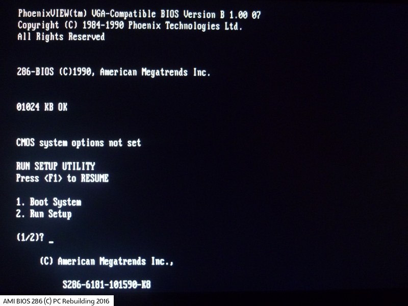
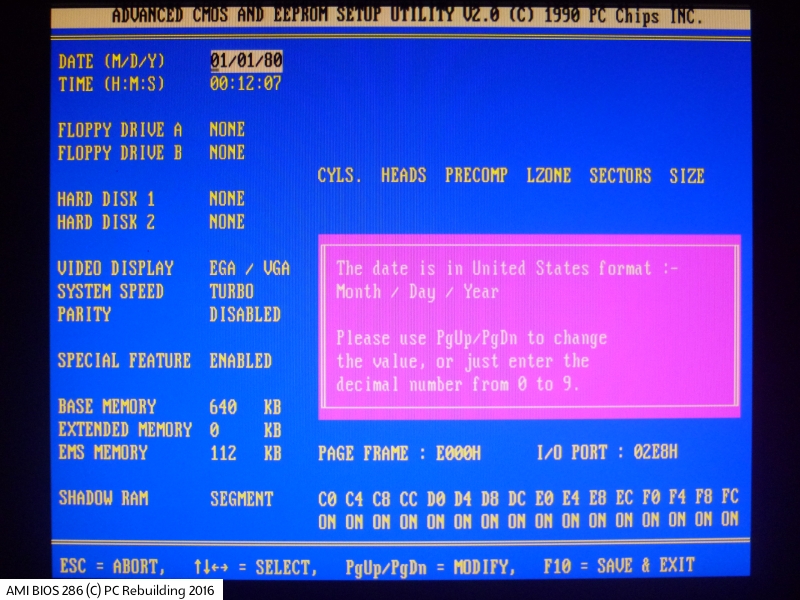
An example of the AMI 286-BIOS startup screen and CMOS Setup Utility main menu
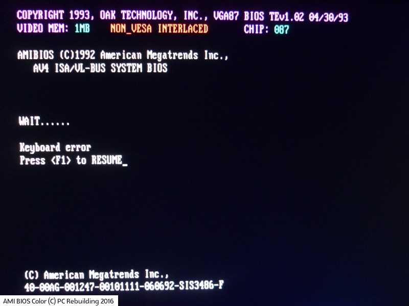
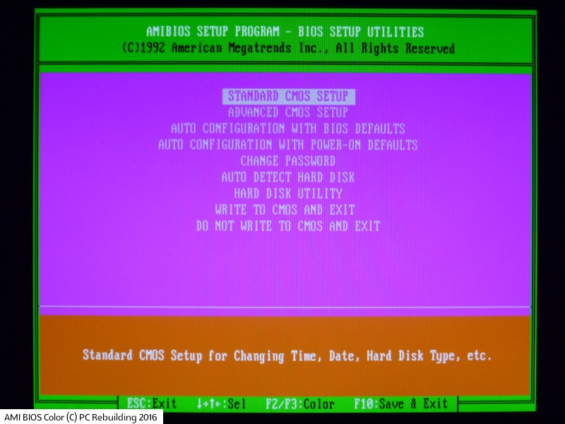
AMI BIOS Color (1992)
The 1992 release of the AMI BIOS Color is probably the one you've seen the most if you've built a 486 PC before. It was very common, and shared a lot of similarities to the Award BIOS of the same era.
An example of the AMI 286-BIOS startup screen and CMOS Setup Utility main menu
WinBIOS (1993)
Love it or hate it (I'm in the latter group), AMI decided to up the ante with a 'Windows-esque' interface for their new BIOS for 1993. It was mouse-driven if a mouse was detected. **UPDATE: Maikel Jansen got in touch to say WinBIOS was actually released earlier than this - he had an Octek Fox 2-based 286 system with a Headland chipset. They bought the system in 1991 and it came with a WinBIOS with a late-1990 BIOS date **
AMI didn't use version numbers in a traditional sense. Their 80s and 90s BIOS were identified by the core release date (not to be confused with the OEM's release date). The first WinBIOS core appears to have been 15th December 1993. While the WinBIOS was released in late 1993, almost all the boards date from 1994 and newer. The latest boards I've seen with the WinBIOS are SuperMicro boards from 1998-99.
An example of the AMI WinBIOS startup screen and CMOS Setup Utility main menu
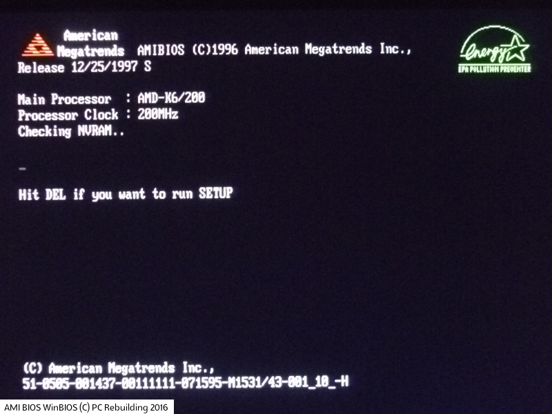
HiFlex BIOS (1996)
AMI moved away from the Windows-like interface in 1996, returning to a simpler text-based CMOS setup utility. I suspect this was because it was much quicker and easier to add in the many custom revisions needed for each manufacturer's motherboard - it probably also kept the needed EPROM storage capacity low.
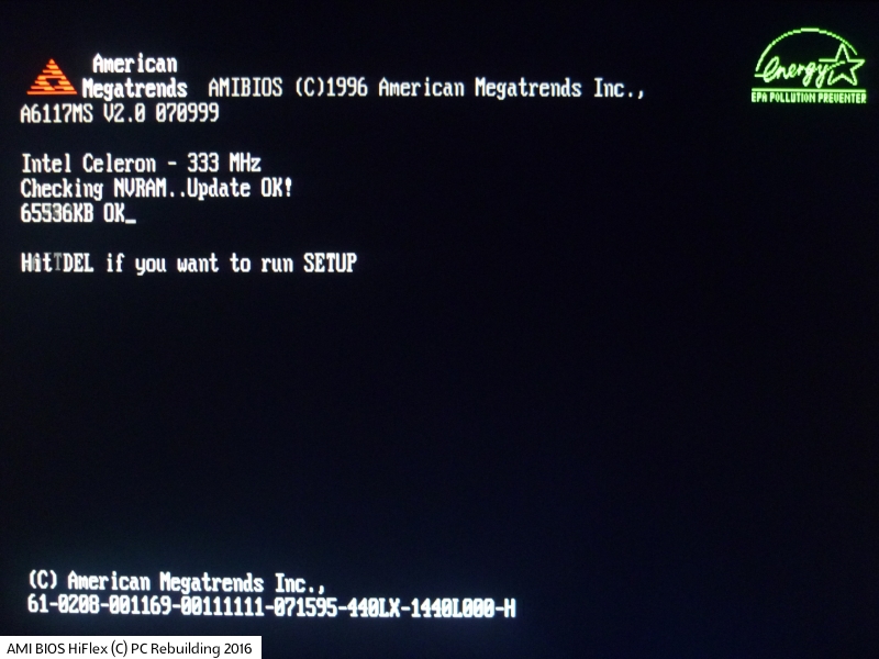
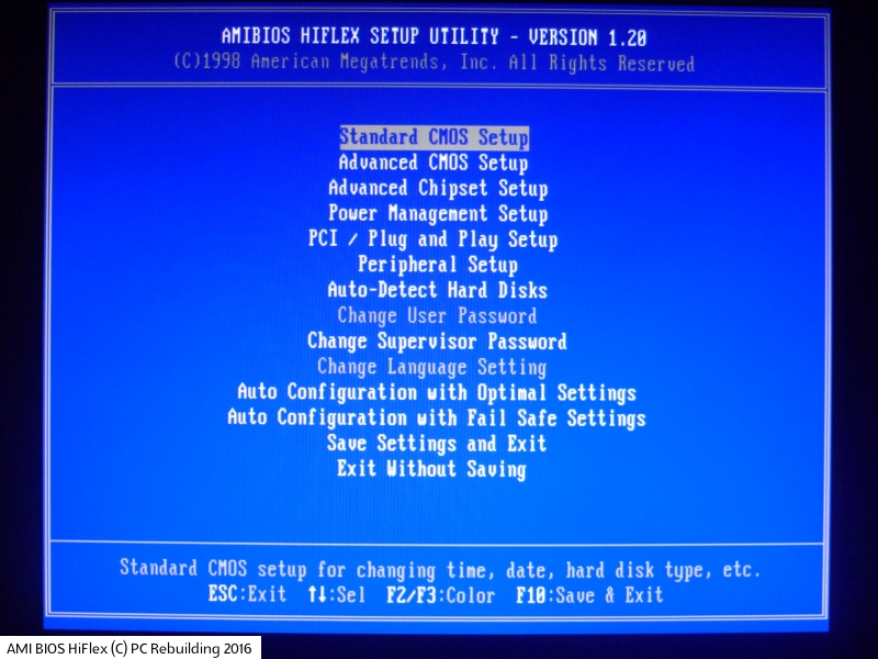
An example of the AMI HiFlex BIOS startup screen and CMOS Setup Utility main menu
AMI BIOS 6.31
AMI BIOS 7.xx
AMI BIOS 8
This was their final version of a true BIOS, before shifting to the new UEFI (Unified Extensible Firmware Interface) standard.
AMI BIOS Beep Codes
The PC BIOS has always used beep codes to indicate an issue during the startup process. This is because a potential problem may occur before the video card has been initialised, so is used to provide an audible indication until the display is ready.
| Beeps | Problem Area | Details |
|---|---|---|
| 1 short beep | Memory | DRAM refresh failure - either the programmable interrupt timer or programmable interrupt controller has failed. |
| 2 short beeps | Memory | Memory parity error in the first 64 KB of memory. Check your DRAM ICs for any that have failed. |
| 3 short beeps | Memory | First 64 KB of memory has failed. Check your DRAM ICs for any that have failed. |
| 4 short beeps | System timer (motherboard) | The system clock/timer IC has failed, or there is a memory error in the first bank of memory. |
| 5 short beeps | CPU | The microprocessor has failed. |
| 6 short beeps | Keyboard | The keyboard controller has failed, causing no Gate A20 signal to be sent to the CPU to put it into protected mode. |
| 7 short beeps | CPU | Virtual mode processor exception has been generated by the CPU due to a fault in the CPU or motherboard. |
| 8 short beeps | Video card | Display memory read/write error. The video card is either faulty or is missing. |
| 9 short beeps | ROM (motherboard) | The BIOS ROM checksum does not match. The BIOS ROM may be defective. |
| 10 short beeps | BIOS | CMOS shutdown register read/write failure - potentially a fault with the BIOS. |
| 11 short beeps | Level 2 cache (motherboard) | Cache error - check your motherboard L2 cache for faults. |
| 1 long, 2 short | Video card | An error was detected in the video BIOS ROM, or a horizontal retrace failure has been encountered. |
| 1 long, 3 short | Memory | The memory test above the first 64 KB failed. Check your DRAM ICs for any that have failed. |
| 1 long, 8 short | Video card | Display test failure. The video card is either faulty or is missing. |
| 2 short | BIOS | POST failure. One of the hardware tests during POST failed. |
| 1 long | BIOS | POST has passed all tests. |
AMI BIOS POST Codes
During the Power-On Self Test (POST) process, the BIOS outputs the current test number it's got to, to port 80h. This can be picked up by a POST code analyzer card, which you'll see being used in a lot of my articles. These analyzer cards are cheap to buy, and are well worth the money if you ever need to diagnose a fault with your PC failing to get through its POST.
The codes below are in listed in the order in which they are processed during startup:
| Code | Versions < 1990 | 1990-1993 BIOS | Color BIOS | WinBIOS |
|---|---|---|---|---|
| 01 | NMI disabled and 80286 register test is about to start. | NMI disabled and 80286 register test is about to start. | CPU flag test | NMI disabled |
| 02 | 80286 register test passed. | 80286 register test passed. | Power-on delay | Power-on delay |
| 03 | ROM BIOS checksum test (32Kb from F8000h) passed OK | ROM BIOS checksum test (32Kb from E8000h) passed OK | Chipset initialization | Soft reset power-on |
| 04 | 8259 programmable interrupt controller has initialized OK | Keyboard controller test passed (with and without mouse) | Soft/hard reset | - |
| 05 | CMOS interrupt disabled | Chipset initialized. DMA and interrupt controller disabled | ROM enable | Disable cache |
| 06 | Video system disabled and the system timer checks OK | Video system disabled and the system timer checks OK | ROM BIOS checksum | Uncompressed POST code |
| 07 | 8253/4 programmable-interval timer test OK | 8253/4 programmable-interval timer test OK | 8042 keyboard controller tested | - |
| 08 | Delta counter channel 2 OK | Delta counter channel 2 initialization complete | 8042 keyboard controller tested | CMOS checksum / CMOS initialization |
| 09 | Delta counter channel 1 OK | Delta counter channel 1 initialization complete | 8042 keyboard controller tested | - |
| 0A | Delta counter channel 0 OK | Delta counter channel 0 initialization complete | 8042 keyboard controller tested | CMOS initialization for date and time |
| 0B | Parity status cleared | Refresh started | 8042 protected mode tested | Initialization before keyboard batch |
| 0C | The refresh and system timer check OK | System timer started | 8042 keyboard controller tested | Batch command to keyboard controller |
| 0D | Refresh check OK | Refresh check OK | 8042 keyboard controller tested, CMOS | Verify batch command |
| 0E | Refresh period checks OK | - | - | Initialize after KB controller batch |
| 0F | - | - | CMOS initialization | Write KB command byte |
| 10 | Ready to start 64KB base memory test | Ready to start 64KB base memory test | CMOS/realtime clock status ok. | Pin 23/24 block/unblock command |
| 11 | Address line test OK | Address line test OK | DMA/PIC disable | Check for <INS> key command |
| 12 | 64KB base memory test OK | 64KB base memory test OK | DMA/PIC initialization | DMA/PIC disable |
| 13 | System-interrupt vectors initialized | - | Chipset/memory initialization | Chipset initialization |
| 14 | 8042 keyboard controller checks OK | - | 8254 PIT timer tested | 8254 timer test |
| 15 | CMOS read/write test OK | ISA BIOS interrupt vectors initialized | 8254 PIT channel 2 timer tested | - |
| 16 | CMOS checksum and battery OK | - | 8254 PIT channel 1 timer tested | - |
| 17 | Monochrome video mode OK | Monochrome video mode OK | 8254 PIT channel 0 timer tested | - |
| 18 | CGA color mode set OK | CGA color mode set OK | Memory refresh test (PIC) | - |
| 19 | Attempting to pass control to video ROM at C0000h | Attempting to pass control to video ROM at C0000h | Memory refresh test (PIC) | Memory refresh test |
| 1A | Returned from video ROM | Returned from video ROM | Check 15-microsecond refresh (PIT) | - |
| 1B | Display memory read/write test OK | Shadow RAM enabled | Check 30-microsecond refresh (PIT) | - |
| 1C | Display memory read/write alternative test OK | Display memory read/write alternative test OK | - | - |
| 1D | Video retrace test OK | Alternate display memory read/write test OK | - | - |
| 1E | Global equipment byte set for proper video operation | Global equipment byte set for proper video operation | - | - |
| 1F | Ready to initialize video system | Ready to initialize video system | - | - |
| 20 | Video test OK | Finished setting video mode | Base 64K memory tested | Base 64K memory test |
| 21 | Video display OK | ROM type 27256 verified | Base 64K memory parity tested | - |
| 22 | The power-on message is displayed | The power-on message is displayed | Memory Read/Write | - |
| 23 | - | - | BIOS vector table initialization | Set BIOS stack, setup before int. vector init |
| 24 | - | - | BIOS vector table initialization | Interrupt vector initialization |
| 25 | - | - | Turbo check of 8042 keyboard controller | Read input port of 9042 chip, clear password |
| 26 | - | - | Global data table for keyboard controller; turbo | Initialize global data for turbo switch |
| 27 | - | - | Video mode tested | Initialize before setting video mode |
| 28 | - | - | Monochrome tested | Set video mode |
| 29 | - | - | Color (CGA) tested | - |
| 2A | - | - | Parity-enable tested | Initialize BUS |
| 2B | - | - | Optional system ROM’s check start | Setup before operational video check |
| 2C | - | - | Video ROM check | Control to optional video ROM |
| 2D | - | - | Reinitialize main chipset | Proc. after optional video ROM routine |
| 2E | - | - | Video memory tested | Display memory Read/Write test if no EGA/VGA |
| 2F | - | - | Video memory tested | Display memory Read/Write test |
| 30 | Ready to start the virtual-mode memory test | Ready to start the virtual-mode memory test | Video adapter tested | Retrace check |
| 31 | Virtual memory mode test started | Virtual memory mode test started | Alternate video adapter tested | Display alternate memory Read/Write check |
| 32 | CPU has switched to virtual mode | CPU has switched to virtual mode | Alternate video adapter tested | Alternate display retrace check |
| 33 | Testing the memory address lines | Testing the memory address lines | Video mode tested | - |
| 34 | Testing the memory address lines | Testing the memory address lines | Video mode tested | Set display mode |
| 35 | Lower 1MB of RAM found | Lower 1MB of RAM found | Initialize BIOS ROM data area | - |
| 36 | Memory size computation checks OK | Memory size computation checks OK | Power-on message display | - |
| 37 | Memory test in progress | Memory test in progress | Power-on message display | Display power-on message |
| 38 | Memory below 1MB is initialized | Memory below 1MB is initialized | Read cursor position | Initialize BUS types |
| 39 | Memory above 1MB is initialized | Memory above 1MB is initialized | Display cursor reference | Display BUS initialization error messages |
| 3A | Memory size is displayed | Memory size is displayed | Display BIOS setup message | Display the hit <DEL> message |
| 3B | Ready to test the lower 1MB of RAM | Ready to test the lower 1MB of RAM | - | Virtual modem memory test |
| 3C | Memory test of lower 1MB OK | Memory test of lower 1MB OK | - | - |
| 3D | Memory test above 1MB OK | Memory test above 1MB OK | - | - |
| 3E | Ready to shutdown for real-mode testing | Ready to shutdown for real-mode testing | - | - |
| 3F | Shutdown OK- now in real mode | Shutdown OK- now in real mode | - | - |
| 40 | Ready to disable gate A20 | Cache memory now on. Ready to disable gate A20 | Start protected mode tested | Prepare descriptor tables |
| 41 | A20 line disabled successfully | A20 line disabled successfully | Build mode entry | - |
| 42 | Ready to start DMA controller test | i486 internal cache turned on | CPU enters protected mode | Enter virtual mode for memory test |
| 43 | - | Ready to start DMA controller test | Protected mode Interrupt enable | Enable Interrupts for diagnostic mode |
| 44 | Check descriptor tables | Initialize data to check memory wrap at 0:0 | ||
| 45 | Check memory size | Check memory wrap, find total memory amount | ||
| 46 | Memory Read/Write tested | Memory write test | ||
| 47 | Base 640K memory tested | 640K base memory write test | ||
| 48 | Check 640K memory size | Determine memory below 1MB | ||
| 49 | Check extended memory size | Determine memory above 1MB | ||
| 4A | Verify CMOS extended memory | - | ||
| 4B | Check for soft/hard reset | Check for soft reset, clear memory below 1MB | ||
| 4C | Clear extended memory locations | Clear memory above 1MB | ||
| 4D | Update CMOS memory size | Save memory size | ||
| 4E | Address line test OK | - | Base RAM size displayed | Display first 64K memory size |
| 4F | System still in real mode | - | Memory Read/Write test on 640K | Sequential and random memory test |
| 50 | DMA page register test OK | DMA page register test OK | Update CMOS on RAM size | Displayed memory size |
| 51 | Starting DMA controller 1 register test | Starting DMA controller 1 register test | Extended memory tested | Above 1MB memory test |
| 52 | DMA controller 1 test passed, starting DMA controller 2 register test | DMA controller 1 test passed, starting DMA controller 2 register test. | Re-size extended memory | Save memory size information |
| 53 | DMA controller 2 test passed | DMA controller 2 test passed | Return CPU to real mode | Enter real mode |
| 54 | Ready to test latch on DMA controller 1 and 2 | Ready to test latch on DMA controller 1 and 2 | Restore CPU registers | Disable gate A-20 line |
| 55 | DMA controller 1 and 2 latch test OK | DMA controller 1 and 2 latch test OK | A-20 gate disabled | - |
| 56 | DMA controller 1 and 2 configured OK | DMA controller 1 and 2 configured OK | BIOS vector recheck | - |
| 57 | 8259 programmable interrupt controller initialized OK | 8259 programmable interrupt controller initialized OK | BIOS vector check complete | Adjust memory size |
| 58 | 8259 programmable interrupt controller mask register OK | - | Clear BIOS display setup message | Clear hit <DEL> message |
| 59 | Master 8259 programmable interrupt controller mask register OK | - | DMA, PIT tested | DMA/PIC test |
| 5A | Ready to check timer interrupts | - | - | - |
| 5B | Timer interrupt check OK | - | - | - |
| 5C | Ready to test keyboard interrupt | - | - | - |
| 5D | Error detected in timer or keyboard interrupt | - | - | - |
| 5E | 8259 programmable interrupt controller error | - | - | - |
| 5F | 8259 programmable interrupt controller OK | - | - | - |
| 60 | - | - | DMA page register tested | DMA #1 base register test |
| 61 | - | - | DMA #1 tested | - |
| 62 | - | - | DMA #2 tested | DMA #2 base register test |
| 63 | - | - | BIOS data area check | - |
| 64 | - | - | BIOS data area checked | - |
| 65 | - | - | Initialize DMA chips | Program DMA unit 1 and 2 |
| 66 | - | - | 8259 PIC initialization | Initialize 8259 Interrupt controller |
| 67 | - | - | Keyboard tested | Keyboard test |
| 70 | Start of keyboard test | Start of keyboard test | - | - |
| 71 | Keyboard controller Ok | Keyboard controller Ok | - | - |
| 72 | Keyboard tested OK | Keyboard tested OK. Starting mouse interface test. | - | - |
| 73 | Keyboard global initialization OK | Keyboard and mouse global initialization OK | - | - |
| 74 | Floppy setup ready to start | Display setup prompt.. Floppy setup ready to start | - | - |
| 75 | Floppy controller setup OK | Floppy controller setup OK | - | - |
| 76 | Hard disk setup ready to start | Hard disk setup ready to start | - | - |
| 77 | Hard disk controller setup OK | Hard disk controller setup OK | - | - |
| 79 | Ready to initialize timer data | Ready to initialize timer data | - | - |
| 7A | Verifying CMOS battery power | Timer data area initialized | - | - |
| 7B | CMOS battery verified OK | CMOS battery verified OK | - | - |
| 7D | Analyzing CMOS RAM size | - | - | - |
| 7E | CMOS memory size updated | CMOS memory size updated | - | - |
| 7F | Send control to adapter ROM | Enable the setup routine if <Delete> is pressed | - | Enable extended NMI sources |
| 80 | Enable the setup routine if <Delete> is pressed | Send control to adapter ROM at C800h to DE00h | Keyboard reset | Stuck key and batch test |
| 81 | - | Return from adapter ROM | Stuck key and batch test | Keyboard controller test |
| 82 | Printer data initialization is OK | Printer data initialization is OK | 8042 keyboard controller tested | Write command byte, initialize circular buffer |
| 83 | RS-232 data initialization is OK | RS-232 data initialization is OK | Lock key check | Lock key check |
| 84 | 80×87 check and test OK | 80×87 check and test OK | Compare memory size with CMOS | Compare memory size with CMOS |
| 85 | Display any soft-error message | Display any soft-error message | Password/soft error check | Password/soft error check |
| 86 | Give control to ROM E0000h | Give control to ROM E0000h | XCMOS/CMOS equipment check | Programming before check |
| 87 | Return from system ROM | - | CMOS setup entered | Execute CMOS setup |
| 88 | - | - | Reinitialize chipset | Programming after setup |
| 89 | - | - | Display power-on message | Power-on display |
| 8A | - | - | Display wait and mouse check | - |
| 8B | - | - | Shadow any option ROMs | Shadow main and video BIOS |
| 8C | - | - | Initialize XCMOS settings | Setup options after CMOS setup |
| 8D | - | - | Reset hard/floppy drives | Initialize mouse |
| 8E | - | - | Floppy compare to CMOS | Reset hard disk controller |
| 8F | - | - | Floppy disk controller initialization | Floppy setup |
| 90 | - | - | Hard disk compare to CMOS | - |
| 91 | - | - | Hard disk controller initialization | Hard disk setup |
| 92 | - | - | BIOS data table check | - |
| 93 | - | - | BIOS data check hat halfway | - |
| 94 | - | - | Set memory size | Base/extended memory size |
| 95 | - | - | Verify display memory | Init. PCI/VLB BUS optional ROM’s from C800 |
| 96 | - | - | Clear all Interrupts | Initialize before C800 optional ROM control |
| 97 | - | - | Optional ROMs check | Control to optional ROM |
| 98 | - | - | Clear all Interrupts | Processing after optional ROM control |
| 99 | - | - | Setup timer data/RS232 base | Setup timer data area/printer base address |
| 9A | - | - | RS232 test; Locate and test serial ports | Set RS-232 base address |
| 9B | - | - | Clear all Interrupts | Initialize before NPU test |
| 9C | - | - | NPU test | NPU initialization |
| 9D | - | - | Clear all Interrupts | Initialization after NPU test |
| 9E | - | - | Extended keyboard check | Check extended KB, KB ID and num-lock |
| 9F | - | - | Set numlock | Issue keyboard ID command |
| A0 | - | Program the cache SRAM | Keyboard reset | Reset keyboard ID flag |
| A1 | - | Check for external cache | Cache memory test | Cache memory test |
| A2 | - | Initialize EISA adapter card slots | Display any soft errors | Display any soft errors |
| A3 | - | Test extended NMI in EISA system | Set typematic rate | - |
| A4 | - | - | Set memory wait states | Program memory wait states |
| A5 | - | - | Clear screen | Clear screen, enable parity NMI |
| A6 | - | - | Enable parity/NMI | - |
| A7 | - | - | Clear all Interrupts | Init. needed before control to E000 ROM |
| A8 | - | - | Control to ROM at E0000 | Control to E000 ROM |
| A9 | - | - | Clear all Interrupts | Init. needed after control to E000 ROM |
| AA | - | - | Display configuration | Display system configuration |
| B0 | - | - | - | Uncompressed SETUP code for hot-key |
| B1 | - | - | - | Copy any code to specific area |
| C2 | - | - | - | Disable NMI, power-on delay |
| C5 | - | - | - | Enable ROM, disable cache |
| C6 | - | - | - | ROM BIOS checksum |
| C7 | - | - | - | CMOS shutdown register test |
| C8 | - | - | - | CMOS shutdown |
| CA | - | - | - | Initialize CMOS date and time |
| CB | - | - | - | Initialization before keyboard batch |
| CD | - | - | - | BAT command to keyboard controller |
| CE | - | - | - | Installation after keyboard controller batch |
| CF | - | - | - | Write keyboard command byte |
| D1 | - | - | - | Check for <INS> key command |
| D2 | - | - | - | Disable DMA and Interrupt controllers |
| D3 | - | - | - | Chipset initialization/auto detect memory |
| D4 | - | - | - | Uncompressed RUNTIME code |
| D5 | - | - | - | RUNTIME code uncompressed |
| DD | - | - | - | Control to shadow RAM at F000:F000 |
| 00 | Call the Int19 boot loader | Call the Int19 boot loader | Call the Int19 boot loader | Call the Int19 boot loader |
Flashing an AMI BIOS
American Megatrends wrote aminf342 and amiflash 8.95, both of which run in DOS for the purpose of flashing BIOS with a core of 6.31 or earlier. For Windows, WinSFI - AMI WinFLASH 3.0.0.6 can also be used for this core or earlier.
For later AMI BIOSes with a core of 7.xx or later, use AFUDOS 4.40 in DOS, AFUWIN 4.48 for Win32, or AFUWINx64 4.48 for Win64.
All of these take a binary .rom file as the new BIOS code.
Note there is always a risk when overwriting an EPROM chip such as the one the BIOS code is stored on. It sounds obvious, but I'll say it anyway: once writing begins, power must be retained until writing is complete. A power cut is probably the most obvious risk here, though if you're overwriting an old EPROM/EEPROM, these ICs do go bad over time. Sometimes multiple successive writes will work in case the first attempt fails. I personally take the chance anyway of using the PC with the BIOS installed and run AWDFLASH or similar, and haven't ever had problems. If you do get into a situation where after an update the PC no longer POSTs, you will need to 'burn' the EPROM/EEPROM using an EPROM burner, such as the TL866 programmer, also commonly seen as the MiniPro, along with the included Windows programming utility, XP8710. For more information on this programmer, see my XT Restoration Project - Part 2.